

Chip breaking in CNC turning, and function of chip breaker
Improper chip breaker or feed rate selection can result in poor chip breaking and continuous chips.
Why should chips break anyway ?
Improper chip breaking can result in poor surface finish, CNC machine downtime to remove the chips periodically, and higher temperatures at the cutting edge. Continuous chips are therefore not desirable.
Why don’t they break ?
In brittle materials chips will break on their own.
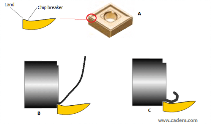
In ductile materials, chips are broken in 3 ways:
1. On their own (like when you bend a piece of wood beyond a certain angle).
2. By pressing against the tool
3. By pressing against the workpiece
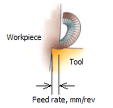
The key is to bend the chip so that one of these happens. This is done by the chip breaker geometry at the cutting edge. Inserts have different cutting edge and chip breaker geometries for different workpiece materials and depths of cut. If the chip thickness is too low, the chip does not even touch the chip breaker and does not curl, as shown in the fig. below. The chip thickness is equal, or almost equal, to the feed rate in mm/rev – equal if the tool’s approach angle is 90 degrees, less if the approach angle is more. So if the feed rate is too low, chip breaking does not happen. This is usually the problem when you are getting continuous chips.
So how does one decide the feed rate ?
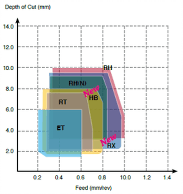
The tool manufacturer’s catalog will have diagrams for various chip breakers, like the one below. ET, RT, etc. are the chip breaker names. The various coloured shapes show the recommended depth of cut and feed rate. If you are using an insert with an ET chip breaker, for example, you must ensure that the depth of cut and the feed rate combination is within the blue shape. It also shows that with ET, you can forget about chip breaking if the feed rate is less than 0.2 mm/rev.
Action point
Chips not breaking ? Look at the chip breaker geometry diagram in the tool manufacturer’s catalog, change the feed rate.
Pic. and text source: CADEM NCyclopedia multimedia CNC training software.


